OST-028: Redline it baby....
Moderators: BOBLOOK, AE25, pufito18
Re: OST-028: Redline it baby....
Good deal! Keep us posted , it's cool these motors have been used in deferent types of motorsports, mine should be back on the road soon and plan to use it as daily , drag and road corse!
-
oldeskewltoy

- Posts: 242
- Joined: Thu Jun 20, 2013 10:17 pm
Re: OST-028: Redline it baby....
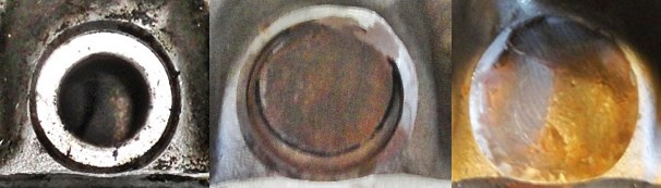
So back to the head.... The port roofs are now blended to meet the delete plate
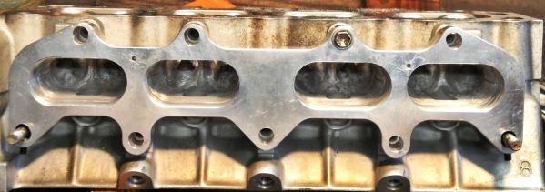
and the injector ports are ready for filling....
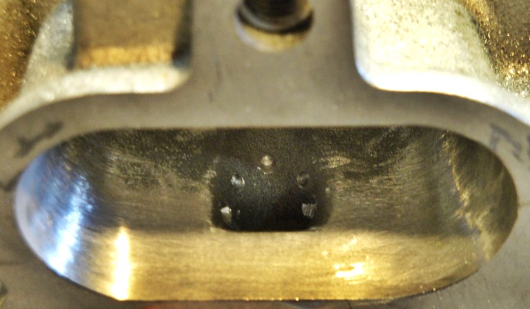
5 - 3/32" holes about 2-3mm deep spaced around the injector port. These, along with the top of the injector port, will be the anchor points for the JB Weld...
Yep JB Weld.... I've done a LOT of research into this. I've looked at some of the other products - Devcon for instance, and none of them offer the temp, and holding capability of the JB Weld - http://www.jbweld.com/faqs/
More to come........
and the injector ports are ready for filling....
5 - 3/32" holes about 2-3mm deep spaced around the injector port. These, along with the top of the injector port, will be the anchor points for the JB Weld...
Yep JB Weld.... I've done a LOT of research into this. I've looked at some of the other products - Devcon for instance, and none of them offer the temp, and holding capability of the JB Weld - http://www.jbweld.com/faqs/
More to come........
-
oldeskewltoy
- Posts: 242
- Joined: Thu Jun 20, 2013 10:17 pm
Re: OST-028: Redline it baby....
more to come........
-
oldeskewltoy
- Posts: 242
- Joined: Thu Jun 20, 2013 10:17 pm
Re: OST-028: Redline it baby....
The above 2 panel was injector port #1...
here is the work on injector port #3
Its just been finished(filling).... note the change in the clay... it is a vital tool in this operation for it allows "adjusting" the volume of JB Weld - by either pulling the clay, or pressing the clay, i can change the level at the port roof.
Also I learned from injector port #1(center in photo above), that it is a bit better to begin filling the port with the clay slightly free to allow the JB Weld to completely fill the injector side of the port. There is enough JB Weld on #1, but #2(far right) is a more complete fill.
I use builders shims in a LOT of my work... they are great for setting the head up for checking chamber volumes, and here I'm using them as applicator/spatula, and as my palate for mixing, and applying. The dental tool helps remove the clay, or as much as I can... the spent tubes of JB Weld... and my finger! A wet finger allows me to shape and fill the voids... I prefer to use water... but saliva works in a pinch
more to come.......
here is the work on injector port #3
Its just been finished(filling).... note the change in the clay... it is a vital tool in this operation for it allows "adjusting" the volume of JB Weld - by either pulling the clay, or pressing the clay, i can change the level at the port roof.
Also I learned from injector port #1(center in photo above), that it is a bit better to begin filling the port with the clay slightly free to allow the JB Weld to completely fill the injector side of the port. There is enough JB Weld on #1, but #2(far right) is a more complete fill.
and here are a few others....it is a vital tool
I use builders shims in a LOT of my work... they are great for setting the head up for checking chamber volumes, and here I'm using them as applicator/spatula, and as my palate for mixing, and applying. The dental tool helps remove the clay, or as much as I can... the spent tubes of JB Weld... and my finger! A wet finger allows me to shape and fill the voids... I prefer to use water... but saliva works in a pinch
more to come.......
Re: OST-028: Redline it baby....
very nice man I see the 11,000rpm it is very achievable with such meticulous little things that you are doing I like your work man keep it up.

-
oldeskewltoy
- Posts: 242
- Joined: Thu Jun 20, 2013 10:17 pm
Re: OST-028: Redline it baby....
BOBLOOK wrote:Nice work wow 11.000rpm limit ??
Not sure where you got 11,000 rpm limit from...????hemilove wrote:very nice man I see the 11,000rpm it is very achievable with such meticulous little things that you are doing I like your work man keep it up.
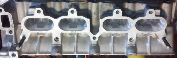
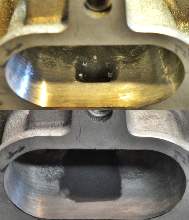
Here is a clearer view of the filled and finished injector ports - the coarse appearance is a 100 grit surface finish to aid in keeping the fuel atomized - closer view of this finish to follow
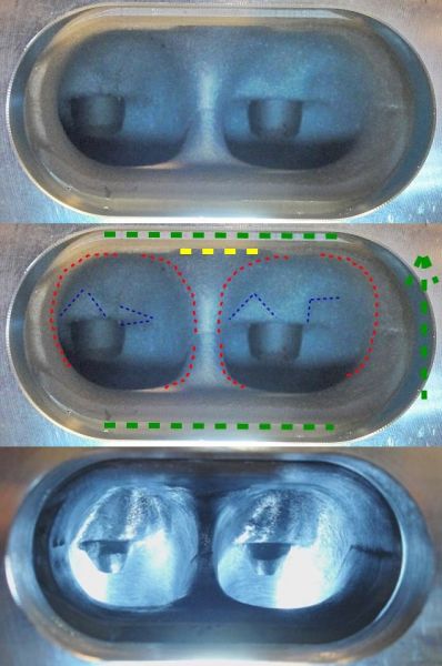
The lower photo was taken with a different camera setting... that is why the bowls appear smaller in the lower view
Another OST 3 -panel... This one shows the bowls, ports, and delete plate. The Green dotted horizontal lines show the excessive size of the delete plate, the green arrow shows that I slotted and "moved" the whole plate up, eliminating the bottom horizontal... but doubling the upper one, so the port roof was tapered to meet the raised delete plate. The dotted yellow line shows the cavity that was the injector port. The red dotted lines attempt (poor drawing skills - apologies) to show the areas ported around the port to bowl transition - the port floor at the transition point to the short radius is left untouched! Finally, the blue lines show the guide boss areas that are blended back for improve volume and velocity, the guides have been knocked back for the same reason.
more to come........
Re: OST-028: Redline it baby....
oldeskewltoy wrote:BOBLOOK wrote:Nice work wow 11.000rpm limit ??Not sure where you got 11,000 rpm limit from...????hemilove wrote:very nice man I see the 11,000rpm it is very achievable with such meticulous little things that you are doing I like your work man keep it up.
From all the work your doing
The day we learn to think
-
oldeskewltoy
- Posts: 242
- Joined: Thu Jun 20, 2013 10:17 pm
Re: OST-028: Redline it baby....
its just getting there.... more fun... see belowBOBLOOK wrote:
From all the work your doing
so... the head is mostly finished... porting wise. My client has ordered a set of Toda valve springs, when they arrive, I'll be re-assembling... and setting the valve clearances for the clients Pon cams.
In the mean time.... the manifold/delete plate "compromise" needs improving... #1 and #4 intake paths are pretty crappy... actually really crappy! If nothing is done... the air speed coming out of the carbs will slow dramatically making low rpm operation less than enjoyable.
Remember... this is the problem.....
oldeskewltoy wrote:
....lets looking at the problem from a different perspective....
The red lines represent the air path from the carb mount flange to the valves. The carb spacing is wider than the ports, and leads to the awkward set up you see.........
So I got to thinking..... what if.....


Above is a bit of an extreme... and is difficult to pull off because the correction passes through 3 different sections of the intake - the manifold, the delete plate, and the head... but the idea is spot on.
A more practical way would be to exclude the head, but to try and correct the intake and delete plate.
First... the manifold surface is not flat... so off to the machine shop to get a minimal machining to get it flat
Then back to my friends mill......
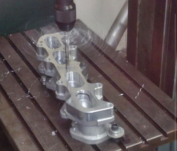
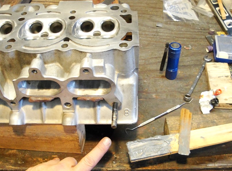
Besides where the bit is currently drilling, can you see any other "new" holes?
Here is a bit better perspective...
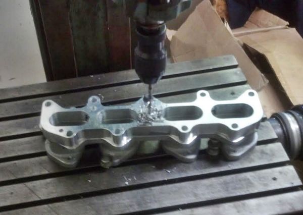
And finished.... 5 new holes from the back side of the delete plate... each hole needing to be drilled 3 times (once for tapping, once for thread passage, and finally for recessed Allen bolt head)
I can now permanently attach the delete plate to the manifold - and when I do make it permanent I'll use red FIPG to seal the two.
Prior to making them permanent, I'll need to add some anchor points inside the manifold, and the delete plate for the filler to affix too.
So... here is the idea....
The black dots are small random drillings about 1mm in depth, the "T" is a small flat head screw embedded in the deepest part of the correction
and from another perspective... the red arrow shows where I'll drill for the flat head screw, the red dots are the 1mm deep random drillings for anchoring.
The green "slice" inside shows the significance of the change.
LOTS more to come.........

Re: OST-028: Redline it baby....
Wow good write up so far..
Tuner, Builder and Racer. Hit me up for all you needs 2/3tc, 3SGTE or 2RZ custom fabbed parts.
Paypal luzunaris99@gmail.com
Paypal luzunaris99@gmail.com